Search

Submersible Connection Deep Well Pump Basics

Use the Submersible Deep Well Pump System if your well specs meets this scenario:

SCENARIO #1
Static Water Level:250′ or less
Electric Submersible Pump Installed:Yes
Well Casing Outside Diameter:4″ or more
Water Exits Well Through:Top of well cap
Freezing is an Issue:No

Select the Submersible Connection Deep Well System when…

  • Well has a Static Water Level up to 250 feet.
  • There is an electric submersible pump in the well, the well casing diameter is greater than or equal to 4”, and the water exits the well through the top of the well cap.
  • Freezing is not an issue.

Details

The Bison Pumps Submersible Connection Deep Well Pump System is a Side-By-Side system (Side-By-Side Deep Well Pump Basics) that installs in the same well casing as your electric submersible pump system. It is NOT a Freeze Proof pump system due to the water from the electric submersible pump exiting the well above ground. It can deliver you with Pressurized Backup Water when used in conjunction with the Pressurizing System. This provides you with water inside your home accessible to any water feature such as a toilet or sink. It can lift water from 250 feet deep using the standard handle or up to 300 feet with the addition of the Heavy Duty Pump Head option. This pump system is recommended when there is sufficient space inside the well casing and the water from an electric submersible pump system exits above ground.

Submersible Connection Deep Well Pump
Water Output Through Top of Well Cap

The Bison Pumps Submersible Connection Deep Well Pump System with the Standard Deep Well Pump Adapter welded on is used for this pump system. It is designed for wells with an electric submersible pump that has the water output exiting the well through the well cap. When this situation occurs, the well pump adapter must be modified to accommodate the water connection both inside the well casing coming from the electric submersible pump and topside where the water exits. Since the well pump adapter will be built to match the pipe size coming from the electric pump, we will need that information when designing the system. In most cases, the water exiting the well is directed to go a certain direction. For example: most are connected to a pipe that goes straight to the home well system. We have to build the well pump adapter to match the direction of the system as it is designed to flow. This may also cause a need to move the handle orientation, especially if the well is inside a well house where movement is restricted. Therefore, we require customers to complete the Spout, Handle and Water Outlet Orientation Form at the time of placing the order. This ensures that all parties are clear regarding the orientation of these items.

Bottom Nipple and Top Elbow Connections on Submersible Deep Well Pump Adapter

This well pump adapter will include a connection nipple that corresponds to your electric submersible pump’s water output pipe size welded to the bottom of the well pump adapter.  On the top of the well pump adapter will be a welded-on elbow, in the orientation requested, to connect to your outgoing water pipe from the electric pump. This elbow will also correspond to the pipe size used by the customer above ground to feed their water system.

This system works with well casing diameters from 4” up to 8” (special order above that size). However, for well casing diameters below 5”, depending upon the size of the pipe from the electric submersible pump and other factors, we may have to recommend one of our Stacked Deep Well Pump Systems.

Top View of Submersible Connection Pump Adapter

This well pump adapter replaces your well cap and provides a seal to protect your well water from contaminants. The adapter has one 3/4” NPT threaded port for wires from an electric submersible pump to exit the well. Another port, 1/2” NPT (3/4” if pump is installed in Michigan) is for the Vent Plug.  There are four bolt holes for the bolts that hold the bottom plate kit to the well adapter.

The bottom plate kit shown below provides the seal for the well. It consists of a rubber gasket and stainless-steel bottom plate. The rubber gasket is compressed by the bottom plate when the four bolts that are attached to it and the well adapter are tightened (see animation below). This gasket can expand to create a seal up to 1/4”. Therefore, we must resize the gasket for every 1/4” change in the inside diameter of the well casing. This is why it is so important to provide us with an accurate inside diameter measurement.

Bottom Plate Kit
Rubber Gasket Compressed by Bottom Plate

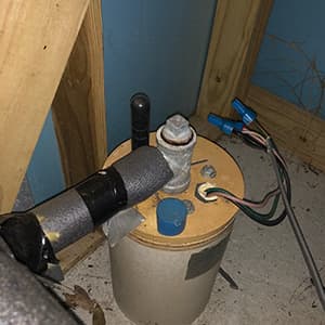
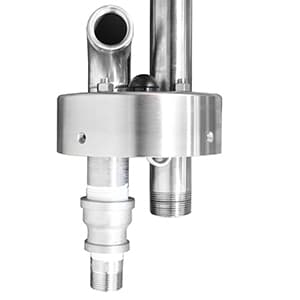
Wires from your electric submersible pump must exit the well. They can exit through the side of the well casing if permitted in your area. If not, or if you don’t choose that option, then the wires can exit through the port hole provided in the top of the well adapter. Bison offers a conduit system for either approach: Conduit El – Top Mount or Conduit El – Side Mount.

Socket-Set Point Cups and Covers

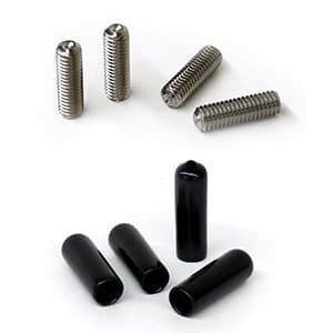
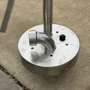
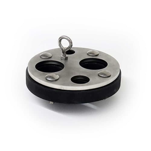
Each well pump adapter covers a range of outside diameters of the well casing, for example the 6” covers from just below 6” to just over 7” in diameter. Four all-thread Socket Set-Cup Points with Covers are provided to address these size differences. When the well pump adapter is mounted to the well casing, you will thread the bolts through the four holes provided in the side of the well pump adapter. These will apply pressure against the well casing providing more stability for the pump head. Plastic covers are provided to protect the all-thread Socket Set-Cups.

Additionally, to further protect your investment, we can add a Tamper Proof option to this style of well pump adapter. The adapter will be connected directly to the well casing with security bolts. This system protects against unwanted removal of the pump head.

Drop Pipe and Rod

Each Bison Pumps Side-By-Side Submersible Connection Deep Well Pump System comes with enough eight (8) foot sections of Drop Pipe and Rod to reach approximately 20 feet below the static water level. This depth allows for fluctuations in the water table and ensures that the cylinder will be below the water surface. The size of the Drop Pipe is typically 1 1/4” but we do offer and recommend 1” for certain applications. This would be where inside casing space availability is a concern or the static water level exceeds 160 feet.

Note that the deeper the static water level is, the more drop pipe will be required. This directly impacts the cost and design of the system. This is why a fixed cost for a pump system cannot be provided. Each pump system is unique to the customer’s well specifics. 

Cylinder

One appropriately sized cylinder is included in a Side-By-Side Submersible Connection Deep Well Pump system. In a Lift Pump system, like the Side-By-Side Submersible Connection, the actual “pump” is the cylinder. This is the device that creates the vacuum to draw water into the water inlet and then uses its piston assembly to lift the water up the drop pipe. In a Side-By-Side application the size of the cylinder is determined by space available inside the well casing and the static water level. We use this Standard Cylinder Selection Chart to determine the appropriate size for each customer’s situation.