A deep well lift pump system consists of three primary components: pump head, drop pipe & rod, and a cylinder. The Bison Pumps systems also come with a few extra installation items such as the Installation Paddle and Rod Retrieval Tool.
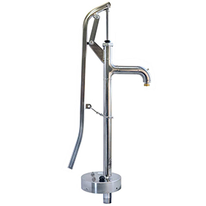
Pump Head
The pump head (as shown above) consists of a pump body, water inlet, spout, lift rod, and handle. When the pump handle is raised, the lift rod is lowered and vice versa. That is the primary function of this device: to move the lift rod up and down. The water inlet is where the pipe that connects the pump to the water source is attached. It is a 1 1/4” NPT threaded nipple. The bottom of the lift rod is a female connection used to connect the lift rod to the drop rod/sucker rod. It has a 3/8” female connection that mates to the 3/8” drop rod.
Drop Pipe & Rod
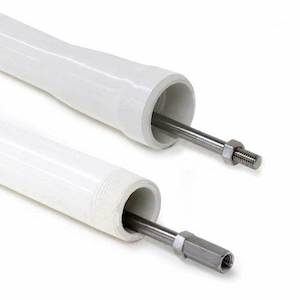
A deep well lift pump system also includes Schedule 120 PVC pipe as the drop pipe (as shown above). The drop pipe connects the pump head to the cylinder so that water can flow from the source in the well to the pump head. The pipe used must be rigid not flexible. When the piston is moved up, flexible pipe would collapse under the compression pressure created during the stroke. This pipe comes in two sizes, 1 1/4” NPT or 1” NPT and is eight (8) feet long. The PVC pipe is threaded and therefore has a male and female end. The female end has a molded coupling that aligns the pipe for easy installation. By using Teflon tape on the threads, only hand tightening is required to form a seal.
Note: Bison Pumps uses Schedule 120 PVC which is much heavier duty than many systems use. This is to prevent the PVC pipe from stretching. The pipe and the rod must be the same length or the pumping action will not function properly. Excessive weight stretches the thinner wall PVC over time causing pumping issues down the line.
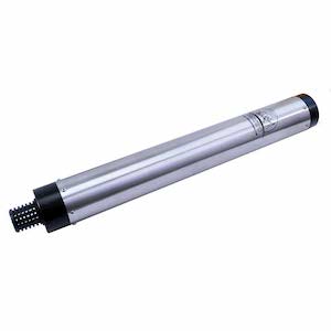
Inside the drop pipe is the “rod/sucker rod” which is 3/8” 304 stainless steel rod with hardware for both a male and female connection. The rod’s function is to connect to the pump head’s 1/2 inch diameter lift rod, using the male end connection, on top of the well casing and the cylinder piston rod, using the female connection, at the other end. This means that there is a stainless steel rod that runs from the bottom of the pump head all the way to the cylinder, 20 feet below the static water level. During pumping this rod is lifted along with the water.
Cylinder
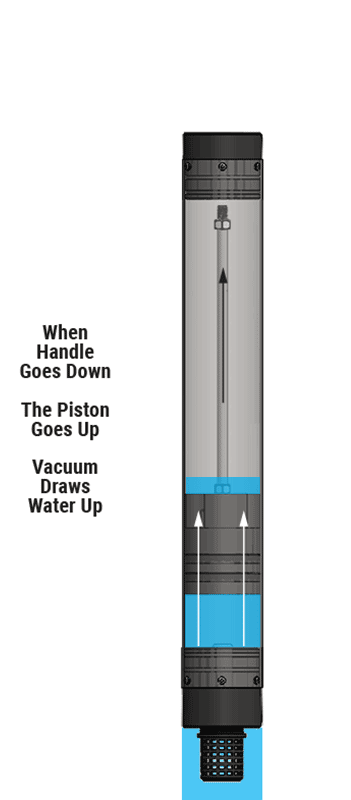
A cylinder consists of a stainless-steel body, a piston assembly, top cap, end cap and filter (as shown above and in the Exploded Cylinder Diagram). This is the pumping device that actually lifts the water to the surface. When the pump’s handle is raised (see image A below), the piston assembly moves to the bottom of the cylinder body. Water in the cylinder body flows past the piston through the one way check valve located inside the piston body. Once at the bottom, the water is above the piston. When the handle is moved down (see image B below), the piston assembly is raised up. When this occurs, two things happen. First, the water above the piston is lifted up into the drop pipe. This creates a vacuum below the piston. This vacuum draws water through the one way check valve located in the end cap filling the cylinder body below the piston.
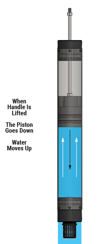
This process is repeated until the water being lifted reaches the pump body. When the water reaches the pump body it will eventually reach the spout and flow out of the pump body creating the water flow from the well.
The one way check valve located in the end cap of the cylinder prevents the water in the cylinder and pipe from draining down. This results in the pump holding its prime. This means that you do not have to lift the water from the cylinder to the spout each time that you use the pump system.
Freeze Proof
Water is in the pump head during pumping and if it remained there it would freeze if left in the elements. To prevent this from happening a “weep hole” is drilled into the drop pipe just below the frost line. This process is described in detail here Freeze Proof. This means that there is no water in the system above the frost line and therefore the system cannot freeze.
Summary
The handle on the pump head moves the lift rod up/down which moves the rod/sucker rod up and down which in turn moves the cylinder piston assembly up/down. This action loads the cylinder with one stroke’s worth of water that is lifted up the system when the handle is moved down. This is why there is pressure on the handle when bringing it down. You are actually lifting the water and rods in the drop pipe on each stroke. Therefore, as the static water level gets deeper more drop pipe and rod are required to reach the water. That means there is more water and rod to lift as the well’s static water level gets deeper. We only recommend our Deep Well Lift Pump Systems to static water levels of 250’ or less due to the extreme weight being lifted. To go beyond that depth we feel it is necessary to increase the strength of the pump head to handle the additional weight. In addition, we extend the length/style of the handle to provide more leverage. This is our Heavy Duty Pump Head option. The rest of the system remains the same. With this option installed the pump system is capable of drawing water from a static water level of 300 feet.